Detailed guides for laser cutting, bending, welding, machining and powder coating. Read the complete chapters online or download the expanded PDF edition in English.
Laser cutting separates the part from sheet metal along a programmed path. The beam heats the material locally and assist gas helps remove it from the cut. The resulting geometry is flat; the part thickness comes from the selected sheet. This operation produces external profiles, holes, slots, cut-outs and blanks for subsequent operations.
What CAM programming does
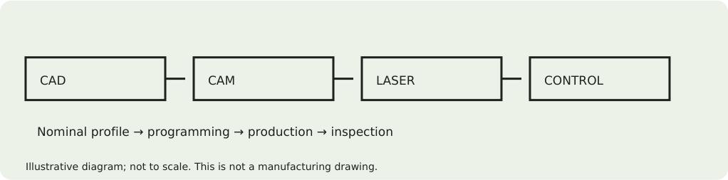
The CAD file is checked, nested on the sheet and converted into a machine program. The programmer sets lead-ins, cutting sequence, kerf compensation and any micro-joints. These are process features, rather than details the customer should automatically add to the drawing.
From contour to product
A bracket may require cutting, bending and coating. A flange may need boring, tapping and dimensional inspection after cutting. Identify the function of the part when requesting a quote: the same CAD shape may require different manufacturing routes when tolerances or appearance requirements change.
02 / Laser, waterjet or plasma?+
Choosing a technology
This comparison helps select a suitable process; it is not an inventory of LaserMet machines. For the service covered by this guide, LaserMet confirms laser cutting within the stated limits. Requests requiring another process are assessed separately.
Why the same rules cannot be transferred
Cut width, heat-affected zone, taper and edge quality depend on the process. Results obtained on one machine or material do not automatically define the result for another setup. Compare costs for the complete part, including finishing and precision operations.
Laser, waterjet or plasma?
Process
Characteristics
When to consider it
Laser
Local heating, 2D profiles; process-dependent kerf
Sheet metal, parts with many profiles and details
Waterjet
Jet cutting, possibly with abrasive; without the heat-affected zone associated with laser cutting
Materials or geometries where thermal effects are critical
Plasma
Thermal process for conductive materials; different detail and edge characteristics
Parts where thickness and cost matter more than fine details
03 / LaserMet capacity and sheet format+
Working format
3,000 × 1,500 mm. The part must allow process margins and support; sheet format does not automatically equal the maximum usable part size.
Maximum thicknesses
Steel: 12 mm. Stainless steel: 8 mm. Aluminium: 6 mm. Grade, material condition and availability are confirmed in the quote. State, for example, S235JR or 304 stainless steel, rather than simply “metal”.
Process result
Laser cutting produces flat profiles. Threads, precision bores, chamfers and sealing surfaces may require separate operations. Specify edges and appearance in the drawing.
LaserMet capacity and sheet format
Material
Maximum laser thickness
Nominal working format
Steel
12 mm
3,000 × 1,500 mm
Stainless steel
8 mm
3,000 × 1,500 mm
Aluminium
6 mm
3,000 × 1,500 mm
04 / Raster, vector and 3D models+
Raster: an image is not manufacturing geometry
JPEG, PNG and scans are made of pixels. They help identify appearance or discuss an idea, but do not reliably define dimensions and cutting coordinates. An enlarged or reduced photograph can retain its appearance while losing scale. Redraw and check dimensions before production.
Vector: coordinates and profiles
DXF and DWG can contain lines, arcs and polylines with measurable dimensions. However, a vector file can contain open contours, duplicate lines, blocks or incorrectly scaled geometry. The correct format is necessary, but does not by itself guarantee a correct drawing.
3D model: shape plus instructions
STEP/STP represents solid geometry and is useful for bent or machined parts and assemblies. Also specify tolerances, threads and finishes in the dimensioned PDF. STL describes a mesh and does not replace a precision solid model for this quotation workflow.
Raster, vector and 3D models
File
Recommended role
DXF
2D cutting profile, in mm at 1:1 scale
STEP / STP
3D geometry for checking and multiple operations
Dimensioned PDF
Material, tolerances, revision, finish and instructions
Image
Visual reference; verified geometry is required
05 / CAD export: steps that prevent errors+
DXF at 1:1 scale
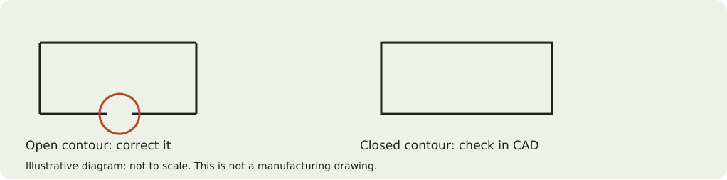
Export in millimetres, with one part per file and closed contours. Remove duplicate lines, isolated points and zero-length segments. Check a known dimension after export.
Separate geometry from instructions
The cutting DXF contains the profile. The dimensioned PDF contains tolerances, material, revision and finish. Put bend or marking lines on separate layers and identify them explicitly.
Other files you can send
STEP for 3D geometry; DWG and PDF for assessment. A photograph or scanned PDF requires redrawing and dimensional verification. Instant estimates are available for eligible DXF files; production follows technical review.
One system of units
Check both model units and export settings. A 100 mm dimension exported in inches may be misinterpreted if the unit is not preserved. Measure a known dimension in the reimported file; the filename does not prove the scale.
Compatibility
For native SOLIDWORKS, Inventor or other models, also export STEP. For 2D drawings, export DXF. This reduces dependency on software versions and proprietary features. Accepting a file does not mean every format qualifies for instant pricing.
06 / CAD software and choosing an export+
No particular application is required
LaserMet needs geometry and verifiable requirements, rather than a particular design program. You can work in a 2D application or 3D modeller, then export neutral files. A native file may help with changes, but also send DXF or STEP together with a dimensioned PDF for assessment.
Flat pattern versus presentation drawing
For bent sheet metal, export the flat geometry from a verified unfolding function, rather than a projected view of the bent part. Decide whether bend lines are excluded from the cutting DXF or retained on a separate layer with explicit instructions. Do not automatically export the bounding box as a cutting path.
Checking after export
Open the exported file in a new document. Check scale, contours and the distinction between cutting lines and instructions. When exporting from a presentation sheet, sheet scale may affect the result; a reference dimension measured in the DXF is more reliable than its on-screen appearance.
CAD software and choosing an export
Application / workflow
Useful export
Check
AutoCAD / 2D drawing
DXF of flat geometry
Units, 1:1 scale and selected objects
SOLIDWORKS / sheet metal
Flat-pattern DXF
Bend lines, contours and revision
Inventor / model and sheet metal
STEP; flat-pattern DXF
Final geometry and export scale
Other CAD applications
DXF / STEP + PDF
Compatibility and reimported dimensions
07 / Cleaning geometry and organising layers+
Cutting contours
Keep the geometry flat, at the same Z level, with every contour closed. Remove duplicate lines and partially overlapping segments; they can change contour recognition and calculated length. Check self-intersections, very short arcs and polylines with excessive unnecessary points.
Separate instructions
Dimensions, title blocks, centre lines, hatching and auxiliary views belong in the PDF. For marking or bending, use clearly named separate layers and explain the operation in the request. A red line is insufficient if colour is lost during export or the application interprets it as a cutting path.
Several parts in one file
Preferably send each part separately. If supplying a combined file, explicitly identify each part and its quantity; their arrangement on screen is not the ordered quantity. Do not duplicate geometry instead of providing a parts list.
Cleaning geometry and organising layers
Element
In the cutting DXF?
External contour and openings
Yes, closed and without duplicates
Dimension lines / title block
No; in the PDF
Bend line
Separate layer, with instructions
Marking / engraved text
Separate layer, with the operation identified
Points and auxiliary profiles
Remove unless they serve a process purpose
08 / Tolerances: what to dimension and confirm+
A nominal dimension is not an acceptance range
A 100 mm dimension describes the reference size. The tolerance establishes the permissible range. Specify applicable general tolerances and highlight functional exceptions. An indicative value of ±0.2 or ±0.25 mm does not automatically apply to all LaserMet parts.
Size, form and position
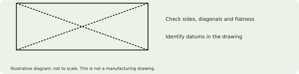
Hole diameter, axis position, plate flatness and edge perpendicularity are different requirements. A part can have the correct diameter but an unsuitable assembly position. Identify measurement datums and avoid contradictory closed dimension chains.
Surface quality and inspection
Identify the visible face and the surface on which a critical dimension is checked. A cut edge may have striations, burrs or taper; assess these for the material and thickness. For fit bores, the solution may be cutting a blank followed by machining, rather than promising identical precision throughout the thickness.
09 / Kerf: cut width and compensation+
What kerf means
Kerf is the width of material removed by the process. It is neither sheet thickness nor a general tolerance. It depends on material, thickness, configuration and parameters. Do not use a fixed 0.2 or 0.3 mm value for all parts or transfer a value from another technology.
Nominal drawing, compensation in CAM
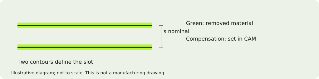
The customer provides the desired contour size. Programming offsets the path so that the resulting edge meets the agreed geometry. Manual compensation added in CAD can accumulate with CAM compensation, producing an oversized part or undersized hole.
Features close to the kerf width
A single-line cut does not automatically define a functional slot of precise width. If a slot must have width s, draw both edges and the ends. Extremely narrow slots, fragile islands and small details require checks of piercing and heat evacuation.
10 / Holes: diameter, webs and edges+
Define what you measure
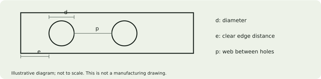
Use d = diameter, t = thickness, e = clear distance between the cut hole and the part edge, and p = web between two holes. Centre-to-edge distance is not the same as e: for a circle it is e + d/2. Confusing these radically changes the geometry.
Preliminary LaserMet criteria
As a conservative initial design screen, start from d ≥ t, e ≥ t and p ≥ t. These are recommendations for initial assessment, not guaranteed process minima or a strength calculation. Holes smaller than sheet thickness, narrow webs and dense perforations can be submitted for review; the workshop determines manufacturability.
Why the remaining material matters
Closely spaced holes and thin edges can be affected by heat and become fragile during handling. For mechanically loaded parts, web size must also be established through structural design. A cutting criterion does not verify bolt loading or in-service part strength.
Holes: diameter, webs and edges
Symbol
Definition
Example at t = 3 mm
d
Hole diameter
Preliminary starting point: d ≥ 3 mm
e
Clear hole-to-edge distance
Preliminary starting point: e ≥ 3 mm
p
Web between contours
Preliminary starting point: p ≥ 3 mm
c
Centre-to-edge distance
c = e + d/2
11 / Slots, notches and narrow cut-outs+
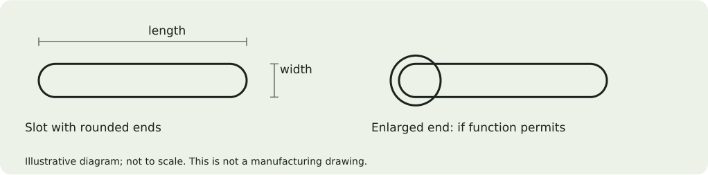
A slot is an area, not a line
Draw nominal slot width and length, including end shape. For an adjustment slot, check bolt diameter, washer access and usable travel length. A very long slot can weaken a part even if it can be cut.
Piercing at the start of a contour
The process requires an entry point. Lead-in and sequence are set in CAM; a narrow slot may provide insufficient space. An enlarged end can be a solution, but do not add it automatically: enlargement must be compatible with part function and appearance.
Edge notches
Deep notches, very sharp corners and slots close to the contour can concentrate stress and leave thin features. Select radii or reliefs for the assembly. For a locating function, dimension from a datum rather than specifying only cut-out width.
12 / Corners and assembly reliefs+
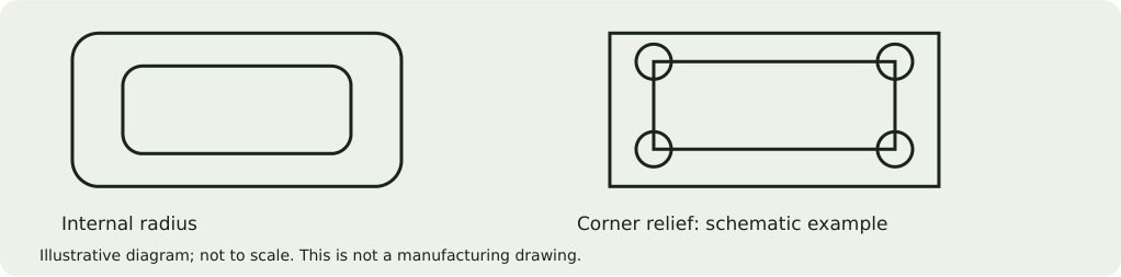
Internal versus external corners
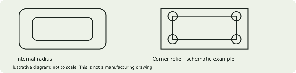
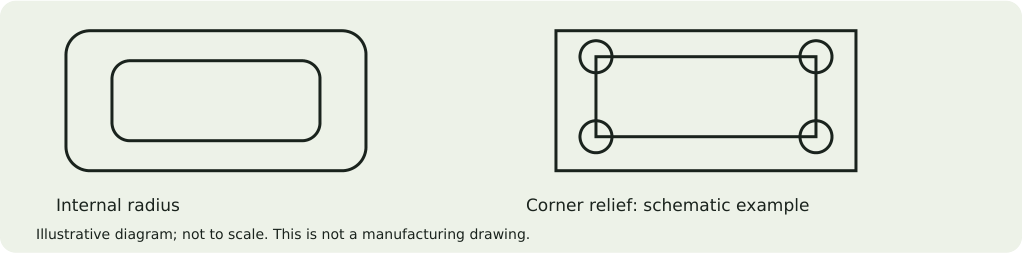
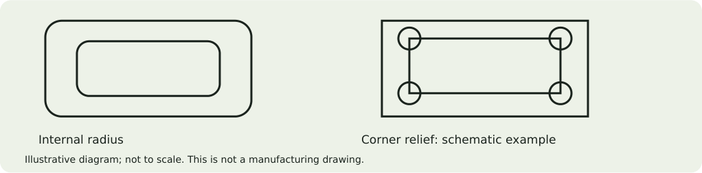
A very sharp internal corner can prevent insertion of an edged component or concentrate stress. A circular dog-bone relief or controlled notch can help assembly. Dimension the shape in the drawing; do not add it to a functional part without agreement.
Radius and strength
Rounding a corner can reduce sensitivity to stress concentration, but does not by itself verify part strength. For a loaded part, choose radius based on function, material, loads and assembly space. No universal thickness multiplier defines the radius for every material and function.
Edges accessible during handling
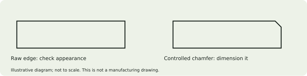
Exposed external corners can be rounded or deburred. State whether burr removal is sufficient or a controlled radius/chamfer is required. Deburring does not automatically produce the same dimension as a machined chamfer.
13 / Tab-and-slot joints and locating protrusions+
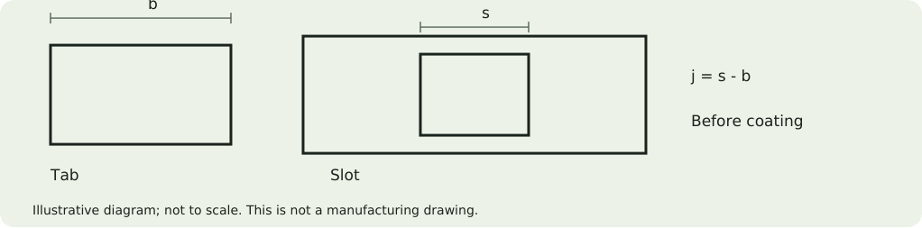
Clearance must be defined
For a tab of width b in a slot s, nominal total clearance is j = s - b. Assembly depends on tolerances of both parts, burrs, flatness and coating. For production runs, validate the joint using the actual material and finish before release.
Local nodes / protrusions
Small protrusions can localise contact or increase friction in a joint. They do not guarantee retention or replace calculations for a loaded joint. An oversized node may block assembly or distort the plate; an undersized one may be removed or affected during cutting.
Locating for welding
Tabs can help assemble subassemblies repeatably, but access for welding and fixtures must remain. Check whether they are visible in the product and whether they must be removed. Do not request an interference press fit followed by welding without assessing the effect on final position.
14 / Cut-out text and shapes with islands+
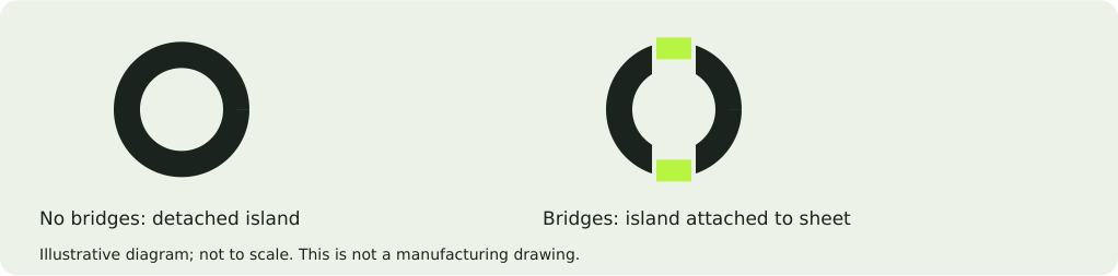
Letters with enclosed areas
In letters such as A, B, D, O, P, Q and R, internal islands detach unless connected by bridges. For negative text in sheet metal, use a stencil design or add bridges compatible with the desired appearance. The same principle applies to logos with isolated areas.
Convert fonts to outlines
Editable text can depend on installed fonts and may be substituted when opened. Export letters as vector geometry. After conversion, check closed contours, duplicates and every island; an “explode” command alone does not guarantee clean geometry.
Legibility and detail
Check minimum stroke and bridge widths at actual scale. Font size is not the width of the thinnest feature. Large letters in a fine font can be harder to manufacture than smaller letters with thick strokes. Approve a sample before production if appearance matters.
15 / Marking, identification and packaging+
Identify the operation, not just the colour
Separate marking text from the cutting path. Explicitly state MARKING, position, size and face in the request. Availability is checked for the project material and finish; this guide does not promise decorative engraving or identical contrast on every surface.
Files and revisions
For logos or graphics, provide vector geometry and a reference PDF. For a part code, specify exact text and revision. If marking must remain legible after coating, assess this before selecting the method and operation sequence.
A label is not permanent marking
Packaging labels help receiving, kitting and batch identification. Specify whether each part, bag or box needs a label. Include code, quantity, revision and any batch number; do not assume full traceability unless agreed in the quote.
Marking, identification and packaging
Solution
Role
What to specify
Marking on the part
Direct identification
Text, position, face, permanence and appearance
Label on the part
Removable identification
Adhesive / permitted area / information
Packaging label
Receiving and separating parts
Code, revision, quantity, kit / batch
16 / Materials: grade, condition and surface+
Sheet steels
S235JR and S355J2 are structural steel grades; DC01 is steel for cold forming. DX51D identifies a category used for coated products, with coating type and mass specified separately. These designations are not interchangeable, even at the same thickness. For high-strength steels, request separate assessment of subsequent operations.
Stainless steel
304 / 1.4301 and 304L / 1.4307 are distinct designations; 316L commonly corresponds to 1.4404. “2B”, “brushed” and “bright” describe the surface and do not replace the grade. Also state brushing direction, visible face and protective film. Film compatibility with cutting is confirmed.
Aluminium
Specify alloy and temper, for example EN AW-5754 H111. Two aluminium sheets of the same thickness can behave differently in bending, welding and finishing. For a part involving multiple operations, select material for the entire route, rather than only cutting.
Materials: grade, condition and surface
Family
Example specifications
Detail not to omit
Steel
S235JR / S355J2 / DC01
Thickness, condition, protection
Stainless steel
304 / 304L / 316L
Surface, film, direction
Aluminium
EN AW-5754 H111
Alloy, temper, subsequent operations
17 / Common thicknesses and availability+
A reference table, not an inventory
The table lists common examples for preparing a request; availability depends on the required grade and condition, supplier and batch. It does not represent LaserMet stock. Thicknesses above cutting limits are not included as a standard offer in this guide.
Format and stock tolerances
The 3,000 × 1,500 mm format is the nominal working limit. Material may also come from other compatible formats, such as 2,000 × 1,000 or 2,500 × 1,250 mm, depending on supply. Actual thickness and flatness follow stock tolerances, which can affect joints and bending.
Customer-supplied material
State grade, thickness, condition, surface and available documents. Rusted, distorted, unidentified material or material with an unknown coating requires assessment. Do not plan production on the assumption that any sheet offcut matches the quality specified in the design.
Common thicknesses and availability
Family
Examples of common thicknesses, mm
LaserMet maximum
Structural steel
2; 2.5; 3; 4; 5; 6; 8; 10; 12
12 mm
Forming steel
0.5; 0.8; 1; 1.2; 1.5; 2; 2.5; 3
Within the 12 mm limit
Stainless steel
0.5; 1; 1.5; 2; 2.5; 3; 4; 5; 6; 8
8 mm
Aluminium
0.5; 1; 1.5; 2; 2.5; 3; 4; 5; 6
6 mm
18 / Deburring, edges and the visible face+
What is removed
Cutting can leave burrs, local dross, lead-in marks or micro-joint marks. Specify the required treatment: burr removal, a handling-safe edge, local grinding or a controlled chamfer. These requirements involve different operations and times.
Tolerances after finishing
Edge treatment can alter local dimensions. Do not combine a functional edge with uncontrolled grinding when fit is critical. Dimension the radius or chamfer where important and state whether dimensions are checked before or after deburring.
Sensitive surfaces
For brushed stainless steel or film-covered sheet, identify the visible face, direction and acceptable scratches. Temporary protective oil on steel is not a final coating and may need degreasing before painting or welding. Select protection and packaging together with the required finish.
Deburring, edges and the visible face
Requirement
Meaning for quotation
Deburring
Removal of residual material from the edge
Dimensioned chamfer / radius
Controlled geometry; operation to be checked
Cosmetic grinding
Defined appearance and acceptable surfaces
Temporary protection
Storage / transport; distinct from final coating
19 / Inserts, nuts and standoffs+
Choose the right family
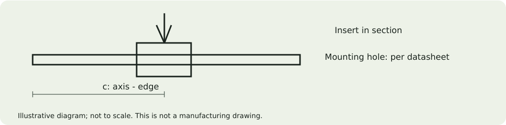
Self-clinching nuts, rivet nuts, weld nuts, cage nuts and standoffs do not share the same installation method. Specify a code or functional requirement, material and installation direction. The workshop checks availability and the operation before confirmation.
Design the hole for the component
Hole diameter and tolerance, minimum thickness, substrate hardness and edge distance come from the insert datasheet. Do not confuse hole-axis-to-edge distance with clear distance from the contour. Do not use thread diameter as installation-hole diameter.
Sequence and surfaces
For press-in inserts, changing the hole edge or installing after coating may affect retention; check conditions for the selected type. Do not automatically deburr or countersink holes dedicated to inserts. Check pressing access and whether bending deformation may affect the hole.
Inserts, nuts and standoffs
Element
Information to supply
Press-in nut / stud
Code, hole, thickness, hardness, direction
Rivet nut
Code, grip range, hole, access
Weld nut
Material, position, weld and protection
Standoff / cage nut
Mounting interfaces and available space
20 / Planning operations after cutting+
Bending
Send the final model and drawing with radii, angles and dimensions. The flat pattern is checked against tooling and actual bending data. Holes near the deformation zone may require relocation, relief or later machining; cuttable geometry does not automatically guarantee bendable geometry.
Welding and machining
For assemblies, include the parts list, locations and welds. For bores, threads or precision surfaces, specify operation and tolerance. Some cases need machining allowance; agree it with the workshop rather than modifying the final profile without notice.
Coating and assembly
Coating changes clearances and diameters. Identify threads, electrical contacts and sealing surfaces requiring masking. If two parts are assembled after coating, check clearance in the final condition. Include assembly and packaging in the same request for a complete price.
21 / Reducing cost while retaining function+
What affects price
Cost depends on material and consumption, contour length, number of piercings, thickness, setup time and subsequent operations. A small, heavily perforated plate may need more cutting time than a larger plate with a simple outline. Weight alone does not describe total cost.
What can be optimised
Use common thicknesses and grades where function permits. Remove nonfunctional details, rather than necessary holes. Group quantities by material and revision, and request prototype and production pricing separately. An approved production sample reduces the risk of reworking an entire batch.
Before confirming an order
Check whether the quote includes material, cutting, deburring, bending, welding, inserts, finishing, inspection and transport. LaserMet minimum order value is €50 excluding VAT; this does not replace calculation for each part. Online estimates for eligible files are followed by technical review before production.
Reducing cost while retaining function
Factor
Useful action
Many internal contours
Review the purpose of perforations
Multiple revisions
Retain only the ordered revision
Unnecessary tolerances
Limit precision to actual functions
Production run
Approve the sample and inspection criteria
22 / Complete checklist and example request+
Files
Clean DXF at 1:1 scale; STEP for 3D geometry where applicable; dimensioned PDF with material grade, thickness, tolerances and revision. The same code must identify the same part in every document. Drawing and model must not contain conflicting revisions.
Manufacturing and appearance
State quantity per part, subsequent operations, visible face, deburring level, inserts and marking. For coating, provide RAL, texture, gloss and masking. For fit components, state the final condition in which the dimension must be met.
Delivery and documents
State requested deadline, packaging and address. Material certificates, inspection reports and traceability must be explicitly requested and confirmed in the quote. For kits, attach the parts list per kit and number of kits; quantities shown in an image are not an order list.
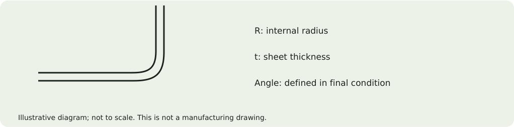
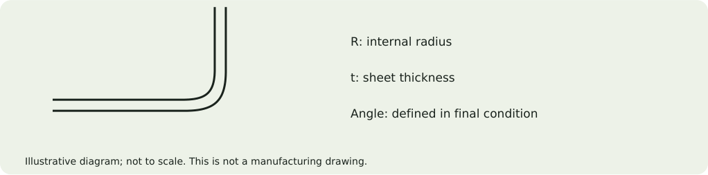
Send the STEP model of the finished part and a dimensioned PDF. Include material, thickness, internal radius, angles and quantity. A DXF flat pattern is useful, but must be checked against production tooling.
Unambiguous dimensions
State whether lengths are internal or external. For angles, show the final angle between faces. Identify the visible face and any surfaces where tooling marks are unacceptable.
Capacity
Permissible length, thickness and geometry depend on material, required force and tooling. Laser cutting limits are not bending limits. Capacity is confirmed for each part.
02 / Radii and unfolding+
Internal radius
A radius of the order of sheet thickness can be a starting point for some ductile sheets, but does not apply universally. Alloy, delivery condition and rolling direction can require larger radii.
Do not set a universal K-factor
The flat pattern depends on achieved radius, die, punch and process. A K-factor taken from CAD must be verified; parts with critical dimensions may need trials and corrections.
Standardise radii
Where function permits, use the same radius and common angles. Reduce tooling changes and avoid very short or closely spaced bends without checking access.
03 / Holes, reliefs and access+
Holes near a bend
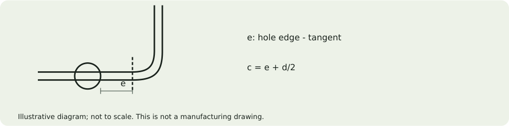
As a conservative preliminary check, keep the hole-edge-to-bend-tangent distance at least 2t. Radius and tooling may require more. Functional holes in the deformation zone may need machining after bending.
Reliefs at bend ends
Provide reliefs extending beyond the deformation zone and avoid corners that can initiate cracks. Agree shape and dimensions with the workshop according to material and tooling.
Tooling access
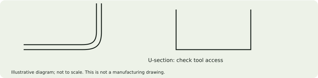
U-shaped parts, enclosed boxes and return flanges may collide with the punch or machine. Check bend sequence; a part may require special tooling or division into subassemblies.
04 / Air bending and tooling selection+
Punch, die and part
In air bending, the sheet is supported by the die and pressed by the punch. The achieved radius and final angle depend on die opening, material, thickness and stroke. A radius modelled in CAD is not automatically achieved simply by selecting a punch with the same radius.
Why each geometry is checked
Required force increases with material strength, thickness and bend length. A short, thick part cannot be compared directly with a long, thin one. Usable machine length does not guarantee every bend along that length. Tooling and access form part of technical confirmation.
Marks and protection
Tooling contact can leave marks, especially on cosmetic surfaces. Identify the visible face and film or protection requirements. Do not specify an unknown film without checking it; it can affect both process and appearance.
05 / Radius, rolling direction and springback+
Material behaviour varies
Alloy, delivery condition, thickness and rolling direction affect bendability. Forming steel, stainless steel and aluminium do not automatically share the same minimum radius. On a low-ductility material, too small a radius can cause cracks even when the CAD geometry is valid.
Springback
After the force is removed, the part can recover partially through elastic springback and the angle changes. The workshop compensates the process for the required final angle. Do not send an “overbent” model to compensate springback without declaring the change, since programming may apply further compensation.
Final drawing and trial
Define the accepted final geometry in the model and drawing. For sensitive materials or geometries, a trial using the actual batch helps determine settings. Acceptance criteria should include angle, final dimensions and appearance, rather than only matching the flat pattern.
Radius, rolling direction and springback
Factor
Possible effect
Alloy and condition
Permissible radius and ductility
Rolling direction
Different sensitivity to cracking
Thickness / batch
Radius and angle variation
Springback
Requires process compensation
06 / Flat-pattern calculation: BA, BD and K-factor+
Neutral axis
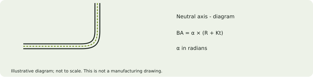
During bending, the outside stretches and the inside compresses. The K-factor expresses the approximate neutral-axis position within the thickness. In a simplified model, neutral arc length is BA = α × (R + Kt), where α is the bend angle in radians, R the internal radius and t the thickness.
The formula has conditions
BA is bend allowance, the bend-zone length in the flat pattern. Do not add it directly to two external dimensions if those already include the corner zone. For external dimensions, bend deduction is calculated using the dimensioning convention and corresponding geometric setbacks. CAD and workshop must use the same convention.
Do not use a universal K
A software K value is an assumption until correlated with tooling and material. Production uses validated data. If the workshop recalculates the flat pattern, the finished model and dimensions remain the reference; change the DXF only after clarifying the revision.
07 / Minimum flange, returns and access+
Flange length
A flange must be supported on the die and positioned. Minimum length depends on tooling opening and shape, rather than thickness alone. A very short flange may fall into the die or need a different manufacturing route. Send its dimension and function before freezing the drawing.
Boxes and U-sections
Check clearance for the punch and part body at every stage. A bend that is feasible individually may become impossible after an earlier flange is formed. Radius, box depth, returns and thickness determine the need for special tooling.
Backgauge access
The part needs a stable locating datum. Cut-outs, angled flanges and asymmetric parts may limit backgauge contact. Designing a reference area or changing bend order can improve repeatability.
Minimum flange, returns and access
Geometry
Required check
Short flange
Support on die
Deep U-section
Punch collision
Return flange
Access and sequence
Asymmetric part
Backgauge datums
08 / Holes near bends: the correct distance+
Measure from the bend tangent
The recommended hole-edge-to-bend-tangent distance is not the distance to an arbitrarily drawn axis in the flat pattern. State the reference explicitly. For a circular hole, centre-to-tangent distance equals clear distance plus d/2.
A preliminary criterion, not an absolute rule
The 2t criterion used for preliminary screening must be checked against radius and tooling. A hole can become oval or pull the edge if the deformation zone intersects it. The permissible limit cannot be determined solely from an image of the part.
Design solutions
Move the hole, change radius or flange, add a verified relief or make the hole after bending. Choose according to function: a clearance bolt hole has different requirements from a locating bore. Nearby inserts also require an access check.
09 / Bend reliefs and enclosure corners+
Why they are needed
When one sheet area bends while its neighbour remains flat, material at the boundary can stretch, tear or bulge. A relief separates the forming zone. Design its shape and length relative to radius and thickness, avoiding a very fragile edge.
Two flanges at the same corner
On an enclosure, neighbouring flanges may overlap or leave gaps. Include thickness, radius and assembly clearance in the finished model. Do not construct a box from zero-thickness faces or assume every corner closes without cuts or welding.
Corner function
For a sealed box, incorporate the relief into the closure and welding solution. For a cosmetic enclosure, assess the visible gap and grinding. For a mechanical support, check remaining material; a relief must not weaken a loaded zone without control.
10 / Tolerances after bending and assembly+
Individual dimensions and accumulated deviations
Length and angle deviations can accumulate in a part with several bends. A dimension between two holes on the same flat face differs from the distance between holes on separate flanges. Identify the surfaces and datums determining assembly.
Effect of angular deviation
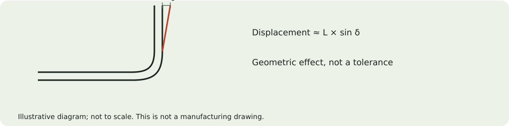
Angular deviation moves a flange end. Approximate transverse displacement for a flange of length L and a small deviation δ is L × sin δ. A long flange is more sensitive than a short one at the same angle.
Inspection dimensions
Dimension clearly after bending and before/after finishing. If function is assembly fit, an agreed trial or gauge can be more relevant than excessive dimensioning of every face. Avoid contradictory dimensions and define requirement priorities in the drawing.
11 / Complete example: bracket and enclosure+
L-bracket
Provide the final model, material, thickness, internal radius, final angle and flange dimensions. Identify mounting holes and their distance from the tangent. If lengths are external, state this convention; do not also supply a flat pattern based on another radius without explaining it.
Enclosure with several bends
Include covers and interfaces in the assembly. Check screw access, clearances, inserts and corners needing welding. For visible faces, specify orientation, surface direction and areas without marks. Use the same revision for model, drawing and flat pattern.
Prototype and production
The prototype checks actual assembly and tooling access. After acceptance, fix revision, material, finish and inspection criteria. A flat-pattern correction must not be applied only to a DXF while leaving the final drawing outdated.
Complete example: bracket and enclosure
Package
Contents
Geometry
Final STEP + dimensioned PDF
Process
Bends, inserts, welds, finish
Inspection
Final dimensions and critical angles
Production
Accepted revision and quantity
12 / Checklist and cost+
Checklist
Final STEP; dimensioned PDF; material; thickness; radii; angles; internal/external dimensions; visible face; functional tolerances; quantities and revision.
Practical example
On 2 mm sheet, a hole edge 1 mm from the bend tangent requires revision. A 4 mm distance passes only the preliminary 2t check; the workshop still checks tooling and radius.
Reducing cost
Standardise radii and orientations, restrict tight dimensions to actual functions and verify the flat pattern before production release. Dimensions after bending have different conditions from those of a flat profile.
Send the STEP model, assembly drawing and parts list. Specify materials, thicknesses, quantity and functional surfaces. Number subassemblies for clear identification.
Weld definition
State joint type, position, size and weld lengths. If using symbols, identify the drawing standard. “Fully welded” does not adequately define functional requirements.
Process selection
Laser, MIG/MAG and TIG have different requirements for joint gap, access and material. Selection is confirmed after reviewing geometry and appearance, strength or leak-tightness requirements.
02 / Joint gap and access+
Part fit-up
Control gap, flatness and edge positioning. Do not transfer MIG/MAG joint-gap tolerances to laser welding. For laser welding, fit-up must be assessed for the actual configuration.
Access for manufacturing
Leave space for the welding head and fixtures. A weld drawn inside a closed corner may be inaccessible; check assembly sequence before finalising parts.
Clean surfaces
State whether material is galvanised, painted or oiled. Preparation and restoration of protection around the joint are established in the quote; the final finish follows the necessary operations.
03 / Distortion and tolerances+
Welds sized for function
Excess deposited metal can increase shrinkage and distortion. Weld sizing belongs to the design; the workshop does not arbitrarily reduce specified welds.
Positioning and sequence
Fixtures and a balanced sequence can control distortion. Dimension reference points and final dimensions after welding. Provide allowance where subsequent machining is needed.
Sealing and verification
For containers or leak-tight assemblies, specify medium, pressure and verification method. Agree inspection and documentation requirements before production; they cannot be assumed from the model.
04 / Laser, MIG/MAG and TIG: process selection+
Selection starts with function
The process is selected for material, thickness, joint, access, productivity and final requirements. A process name does not guarantee penetration, strength, leak-tightness or appearance. Load-bearing or sealed parts need design and verification requirements defined before production.
Laser
Energy is concentrated in a small area, but the result depends on edge fit-up, joint position, material and configuration. Filler use or other operating modes change process requirements. Do not copy a joint gap from arc welding to laser welding without assessment.
MIG/MAG and TIG
MIG/MAG uses a continuous wire electrode and shielding gas; gas type and filler are selected for the material. TIG uses a non-consumable electrode and can include separate filler. Productivity and weld-pool control differ. The workshop proposes the appropriate route, while the drawing defines the required result.
Laser, MIG/MAG and TIG: process selection
Process
Important checks
Laser
Gap, positioning, access, penetration and appearance
MIG/MAG
Gap, filler, access, spatter and distortion
TIG
Access, preparation, filler, shielding and time
05 / Butt, lap and T-joints+
Butt joint
Align the ends and define gap and preparation according to process and thickness. If full penetration is required, state and verify it. Drawing a line between two parts does not automatically define a fully penetrated joint.
Lap and T-joints
For a lap joint, contact length, access and any gap matter. In a T-joint, effective weld thickness and length define the weld requirement. Do not size a weld from a rendering. Identify whether it is single-sided, double-sided or limited to particular segments.
Closed corners
On enclosures, head access and assembly order are decisive. Check access to the root and feasibility of later finishing. For a sealed product, the weld path must be continuous where necessary, with the verification method explicitly agreed.
06 / Defining the weld on a drawing+
Dimensions and symbols
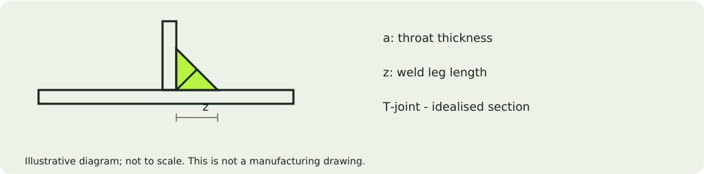
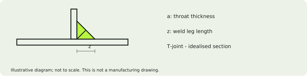
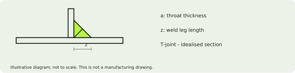
For a fillet weld, throat thickness a and leg length z are different dimensions. For an idealised 90° section with equal legs, a ≈ z/√2. State the correct symbol and size, position, length and any pitch; the workshop checks interpretation before production.
Length, continuity and side
Identify exactly the welded areas, application side and any interruptions. “30 mm weld” may mean one segment, rather than the entire edge. For intermittent welding, define segment count or pitch and location; do not leave this to interpretation of a photograph.
Functional requirement
State whether the weld serves positioning, strength, sealing or appearance. A weld ground flush can have a different final section from an exposed weld. Material removal after welding must be approved for the function and design.
07 / Joint gap, fit-up and part preparation+
Flatness and alignment
Edges must allow repeatable positioning. Check cutting and bending deviations, stock distortion and fixture contact. Forcing nonconforming parts together can introduce stresses and hide a dimensional problem that reappears after release.
Preparation and contamination
Removal of oxides, grease, paint or coatings is determined for the material and process. State whether material is galvanised or has unknown protection. The prepared area must permit welding and finish restoration; a painted surface is not assumed ready for welding.
Gap is a process condition
Opening, angle and bevel are selected for the joint, thickness and procedure. We do not publish a universal maximum gap for LaserMet. If a part needs laser welding, discuss the model and fit-up tolerances before manufacturing all production parts.
Joint gap, fit-up and part preparation
Problem
Possible consequence
Variable gap
Uneven penetration / appearance
Misaligned edges
Changed position and section
Contaminated surface
Affected quality and finish
Forced fit in fixture
Stress and springback after release
08 / Fixtures, tack welding and weld sequence+
Positioning in a fixture
Establish datums determining final geometry and head access. Supports must allow handling and any necessary movement. A fixture improves repeatability but cannot compensate without limit for parts that do not match the drawing.
Tack welding
Tacks hold position before the final weld and form part of the manufacturing plan. Their location and integration into the final weld are established technically. Visible tacks that need removal or finishing must be included in appearance requirements.
Sequence and distortion
Heat and shrinkage can alter angles and dimensions. Segment sequence, alternating areas and fixtures are selected for the actual geometry. For a long or thin-sheet part, a trial is useful to check geometry after cooling and release.
09 / Materials and finishing after welding+
Steel
Material and condition affect preparation, filler and any process measures. High-strength steels or material combinations need separate assessment. This quotation guide does not replace selection of a suitable welding procedure.
Stainless steel and aluminium
Specify grade, condition and surface requirements. For stainless steel, describe the difference between exposed welds, ground welds and restored brushed surfaces. For aluminium, alloy and temper are essential; compatibility and results are checked for the project.
Finishing and machining
Grinding can change weld section and edges. Precision bores or surfaces may be machined after welding where function requires it. Plan final coating after welding and preparation; substrate roughness and marks may remain visible unless corrected.
Materials and finishing after welding
Requirement
Necessary detail
Exposed weld
Accepted appearance and visible face
Ground flush
Permitted areas and final geometry
Brushed stainless steel
Direction and restoration method
Precision surface
Machining before / after welding
10 / Inspection: dimensions, appearance and leak-tightness+
Dimensional inspection
Define final dimensions after cooling, measurement datums, flatness and relationships between parts. Frame diagonals and hole alignment can be critical. For an enclosure, cover position and gasket plane may matter more than overall external dimensions.
Weld quality
External appearance alone does not prove penetration or absence of internal defects. If special inspection, acceptance levels or qualification documents are needed, request them before quotation and obtain explicit confirmation. A faster process does not remove verification needs.
Leak-tightness
State medium, pressure or vacuum, duration and test method where defined by the design. Review the requirement with the technical lead. Visual inspection or a simple test is not equivalent to every pressure-vessel requirement.
Inspection: dimensions, appearance and leak-tightness
Check
Purpose
Dimensional
Geometry and assembly
Visual
Appearance and visible defects
Requested special inspection
Characteristics agreed for the design
Leak test
Specific function and acceptance criterion
11 / Example subassembly quotation request+
Define the deliverable
Instead of “welded frame”, supply assembly code, drawing, parts list, materials and revisions. State whether LaserMet supplies the complete subassembly or welds customer-supplied parts. Identify included cutting, bending, drilling and coating operations.
Assembly requirements
State hole positions, seating plane, contact points and permissible distortion. Include mating parts if available to check screw access and function. A rendering helps orientation, but a dimensioned drawing remains necessary.
Production and acceptance
Separate the prototype from annual production and delivery batches. A fixture can have a setup cost and offer production benefits. After prototype approval, retain the same requirements and documents for the batch; any part change needs a new revision.
12 / Assembly acceptance+
Checklist
Assembly drawing; parts and revisions; materials; weld definitions; final dimensions; appearance; finish; inspection requirements and requested documents.
Function and appearance
A surface ground flush has different requirements from an exposed weld. Identify visible areas and where the design permits weld-metal removal.
Cost and repeatability
Use parts that locate easily, reduce reorientation operations and discuss a production fixture. An accepted prototype helps establish criteria before the batch.
For 3D design and prototyping, also send the sketch, part function and mounting interfaces. The model describes shape; the drawing specifies tolerances, roughness, threads and measurement datums. Include material grade and condition, quantity and revision.
Functional dimensions
Identify fits and contact surfaces. Very tight tolerances on every dimension may require unnecessary machining and inspection. Establish requirements according to each surface’s role.
Confirmed capacity
Maximum dimensions, materials, precision and required axis count are checked for the part. Do not assume every uploaded geometry can be manufactured by the same route.
02 / Milling and pockets+
Internal corners
A cylindrical cutter leaves a radius in internal corners. Avoid perfectly sharp pocket corners; reliefs can accommodate a rectangular component where function permits.
Depth and access
Deep, narrow pockets need long, less rigid tools. Increase radius and opening where possible. Hidden cavities and undercuts require access checks.
Thin walls
Thin walls can distort during clamping and machining. Permissible thickness depends on material, height and geometry; discuss workholding strategy and operation sequence.
03 / Turning, holes and threads+
Rotational parts
Use coaxial geometry where function permits and specify relationships between diameters. Side holes and non-circular features may require additional operations and setups.
Blind holes
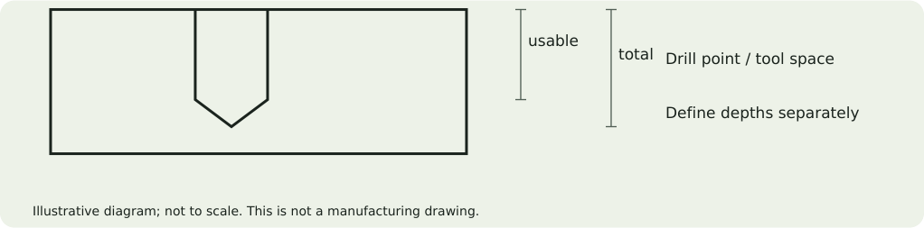
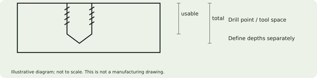
Specify usable cylindrical depth separately from the drill point. Do not implicitly require a flat bottom unless necessary. Long, small holes require chip-evacuation checks.
Threads
State type, diameter, pitch, class and usable length. For example: M6 × 1, usable thread 10 mm; drilling depth is established separately. Specify clearances for the screw and its head.
04 / Selecting stock and the manufacturing route+
Turning or milling
Turning suits many rotational shapes; milling creates faces, pockets, profiles and other geometry. A part may need both, plus drilling or threading. Do not assume an entire part is produced in one setup because the model is a single solid.
Stock
Select bar, plate, section or cut blank according to dimensions, material and operations. Let the workshop establish process allowances compatible with the final drawing. Undersized stock may prevent workholding; excessively large stock increases consumption and time.
Material and condition
Grade, treatment and delivery condition affect machinability and stability. State whether requirements apply before or after treatment. Do not replace an alloy based solely on appearance; substitutions require explicit acceptance.
Selecting stock and the manufacturing route
Shape
Route to assess
Shaft / bushing
Turning + additional operations
Plate with pockets
Milling, drilling and inspection
Sheet-metal part
Cutting + local machining
Welded assembly
Welding + final machined surfaces
05 / Pockets: tool radius and depth+
Internal radius
A cylindrical cutter cannot produce a perfectly sharp internal corner. Corner radius must allow access for a sufficiently rigid tool. Where function permits, a larger radius may reduce passes with small tools. Dimension corner reliefs and check against the component entering the pocket.
Depth and narrowness
Depth-to-opening ratio indicates access difficulty but does not by itself establish a universal limit. Long tools may deflect or vibrate, and chip evacuation becomes harder. State whether pocket shape can change without changing function.
Bottom and surfaces
State whether the bottom must be flat, whether a radius is permitted and where roughness is specified. A sealing surface has different requirements from a weight-reduction recess. Do not impose the same roughness on every surface unless needed.
06 / Holes: drilling, boring and counterbores+
Simple hole and precision bore
A bolt clearance hole and a centring bore have different requirements. For centring, dimension the fit, position and datums. Manufacturing may involve drilling followed by boring, reaming or another operation, according to geometry and tolerance.
Counterbores and countersinks
A cylindrical counterbore defines a head recess or bearing surface. A conical countersink has diameter/depth and angle. Do not confuse a screw-head countersink with a small deburring chamfer. Explicitly dimension functional geometry.
Blind and through holes
State usable depth and whether a conical drill point is allowed. Check remaining thickness to the opposite face or a pocket. Discuss long holes with the workshop; diameter alone does not describe deviation and chip-evacuation risk.
Holes: drilling, boring and counterbores
Operation
Drawing requirement
Drilling
Diameter, position, through / blind
Boring / reaming
Fit and inspection datums
Cylindrical counterbore
Diameter, depth, face
Countersink
Angle, diameter / depth
07 / Internal and external threads+
Complete specification
For metric threads, state M, diameter, pitch, class and usable length; for other families identify the standard and required form. A thread drawn in a model can be interpreted differently unless defined in the PDF. Explicitly state left-hand threads.
Usable depth and drilling
In a blind hole, full thread does not automatically extend to drilling depth. Space is needed for tool entry, thread runout and any drill point. Specify the required usable length; the workshop checks depth and remaining material.
Reliefs and assembly
External threads near a shoulder may require relief for the tool and mating-part seating. Check wrench access, screw head and wall thickness. Thread length is sized for material and load; a generic multiplier does not replace calculation.
08 / Thin walls, long parts and workholding+
Rigidity
A tall, thin wall may distort under cutting forces or clamping. Minimum manufacturable thickness depends on material, height, shape and access. Sometimes operation sequence changes or supports are used; other cases require geometry revision.
Shafts and bushings
A long, thin shaft may require support, while a thin-walled bushing may distort in a chuck. Specify functional diameters and required concentricity relative to datums. Do not treat clamped dimensions as equivalent to dimensions after release.
Workholding areas
The workshop must hold the part safely and reach its surfaces. Geometry without useful clamping areas may need a fixture or sacrificial allowance. State whether temporary holes or marks on nonfunctional areas are allowed; they are not added arbitrarily.
Thin walls, long parts and workholding
Problem
Option to assess
Flexible wall
Greater rigidity / support / different sequence
Long shaft
Suitable support and workholding
All surfaces functional
Dedicated fixture
Clamping marks unacceptable
Protected areas and appearance criteria
09 / Tolerances, datums and roughness+
Size versus geometry
Diameter tolerance does not define concentricity, cylindricity or position. Face flatness alone does not define perpendicularity to an axis. If functional, specify these characteristics in the drawing with identifiable datums and verification conditions.
General dimensions and exceptions
Use general tolerances appropriate to the design and highlight critical dimensions. Tight tolerances may require different tooling, settings, inspection temperatures and measuring methods. LaserMet confirms them per part; this guide does not establish universal precision for all dimensions.
Roughness and marks
Identify surfaces needing roughness control and state the parameter, such as Ra, with units. A “shiny” rendered surface does not specify roughness. Also state chamfers, radii and edges that must not be rounded, so deburring does not affect assembly.
10 / 3D design and prototyping+
Starting from a sketch
Send function, main dimensions, known loads, mating parts and space constraints. Photographs and sketches help, but mounting dimensions must be verified. Defining geometry does not automatically include structural verification or product certification.
What needs approval
Before manufacturing, clarify model, drawing, material, operations and functional criteria. For a replacement part, establish whether to copy measured geometry or design a modified solution. A worn part can provide dimensions that differ from the original drawing.
Prototype versus production
A prototype can validate fit and the manufacturing route. After testing, update every file and approve the production revision. State which tests the customer performs and which checks the workshop performs; a fitting prototype alone does not prove service life.
3D design and prototyping
Stage
Result to agree
Definition
Function, interfaces, dimensions
Design
Model and drawing for approval
Prototype
Fit and agreed checks
Production
Accepted revision and inspection
11 / Cost estimation and a complete request+
More than weight
Time depends on material removal, access, setup count, tools, tolerances and inspection. A light part with deep pockets and many holes may cost more than a heavy part with simple geometry. Stock consumption differs from final mass.
Useful optimisations
Reduce orientations, allow tool-compatible radii and remove unnecessary precision. Avoid nonfunctional thread depths and very fine surfaces where unnecessary. Request a price comparison for actual quantities, rather than only one prototype.
Quotation package
STEP and PDF, material grade and condition, quantity, tolerances, roughness, threads, finish and requested documents. State whether design is included and whether the model is final or can be optimised. Indicative online pricing is technically confirmed before manufacturing.
12 / Inspection and cost reduction+
Checklist
Consistent model and drawing; datums; tolerances; roughness; threads; material and condition; quantity; finish; measurement and traceability requirements.
Revision example
A pocket with sharp internal corners may require another process. Adding a tool-compatible radius, where function permits, simplifies manufacturing.
Cost
Reduce setups, use common holes and threads, and specify fine roughness only where needed. Request prototype and production prices separately; material availability is confirmed.
State RAL colour, texture, gloss and visible faces. RAL code alone does not define texture or gloss. For matching an existing product, provide an accepted sample.
Service environment
State indoor/outdoor use and exposure to moisture and chemicals. Preparation and coating system are selected for material and use; colour does not define corrosion resistance.
Operations before finishing
Plan deburring, welding, grinding and machining before coating. Weld marks or substrate defects may remain visible without appropriate preparation requirements.
02 / Fits and masking+
Coating changes dimensions
The applied layer affects diameters, slots and assembly clearances. Request system thickness in the quote and check final fit. Do not use a universal value for every finish.
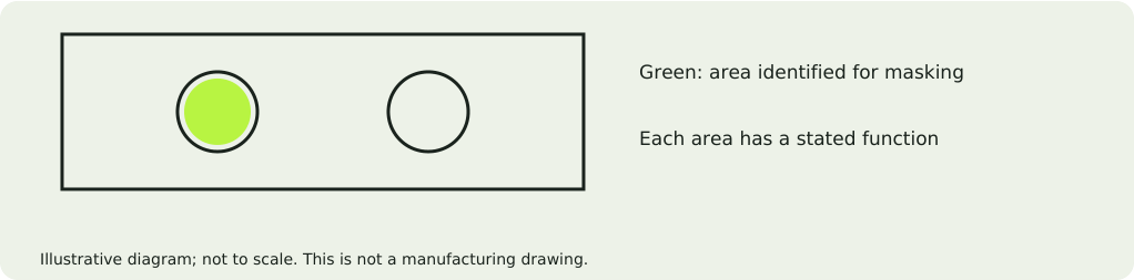
Uncoated areas
Identify threads, contact, grounding and sealing surfaces requiring masking. State whether tolerance is required before or after finishing.
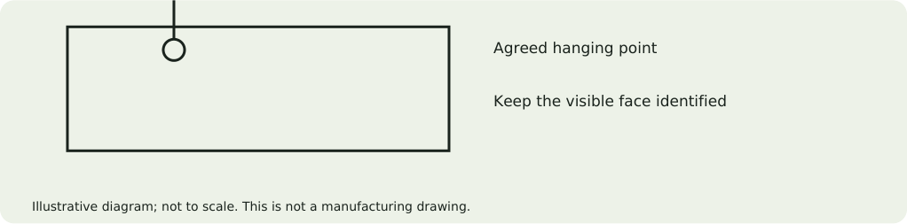
Hanging points
Parts need positioning during the process. Agree hanging holes or points and areas where marks are acceptable, especially on design features.
03 / Material and geometry+
Substrate preparation
Steel, stainless steel and aluminium need appropriate preparation. Do not prescribe identical preparation for every material. State existing coatings and any repairs.
Edges and cavities
Very sharp edges and difficult-to-reach areas can complicate uniform coating. Provide safe edges and discuss deep cavities during design.
Hollow assemblies
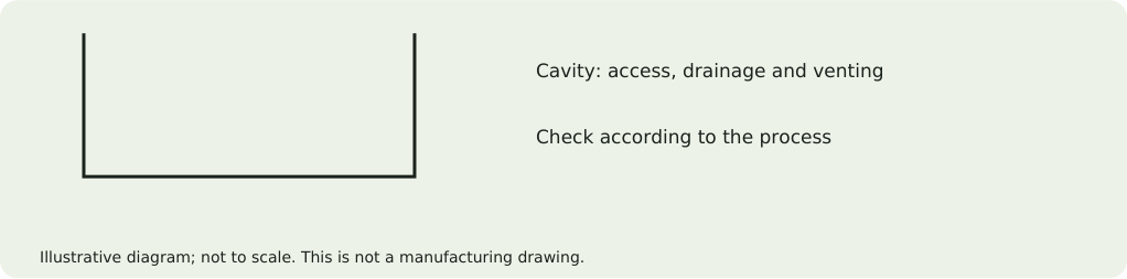
For sections and enclosed volumes, assess ventilation, drainage or access-hole needs with the workshop according to the process. Do not close the geometry before this check.
04 / Coating system, colour and environment+
The system is more than RAL
Electrostatic powder coating applies powder to a substrate, followed by a curing cycle appropriate to the product. Material grade, preparation and powder type affect results. RAL describes reference colour, rather than corrosion protection or overall system performance.
Service environment
State indoor or outdoor use, exposure to water, sunlight, chemicals and installation conditions. Water-retaining surfaces and contact between dissimilar materials can change behaviour. Identical durability is not promised in every environment simply because a part is coated.
Texture and gloss
Describe shade, texture and gloss together. Fine-textured black and smooth glossy black can look different despite sharing the same RAL. For adjacent products, approve a sample and agree comparison criteria.
Coating system, colour and environment
Specification
Example request field
Material
S235JR, stainless steel or aluminium alloy
Environment
Outdoor, water / sun / identified agents
Appearance
RAL + smooth/textured + gloss
System
Preparation and coating confirmed in quote
05 / Surface preparation before coating+
Cleaning
Grease, dirt, oxides and residues can affect adhesion or appearance. Preparation is selected for material and substrate condition. An apparently clean part may retain contamination; state material history, oils and previous coatings.
Cutting and welding
Check edges and weld areas before finishing. Dross, spatter, burrs and sharp corners do not automatically disappear under powder. A coating may emphasise substrate defects; request grinding or surface restoration where appearance requires it.
Special substrates
Galvanised materials, castings and porous surfaces may need particular assessment and preparation. Curing conditions must be compatible with the assembly. State adhesives, plastics and installed components before selecting the process.
Surface preparation before coating
Substrate condition
What to assess
Oiled
Suitable degreasing
Oxidised / rusted
Removal and substrate integrity
Welded
Spatter, marks, corners and flatness
Previously coated
Compatibility or removal
06 / Edges, cavities and surface access+
External edges
Very sharp edges can affect coating behaviour and are undesirable for handling. Provide appropriately prepared edges without changing functional areas. A dimensioned chamfer and simple deburring are distinct operations.
Internal corners and pockets
In electrostatic application, deep or shielded areas can be harder to coat uniformly. Do not assume a cavity interior receives the same layer as the outside face. If internal coating is critical, specify the area and verify process feasibility.
Enclosed volumes
Washing, drainage, drying, ventilation and heating require geometry checks. Process holes are established according to process and product. Avoid liquid-trapping cavities or configurations that cannot be cleaned or inspected; approve any geometry change before manufacturing.
07 / Layer thickness and assembly clearances+
Specified thickness
Layer thickness is established for the coating product and system. We do not publish a universal thickness for every part. If critical, agree the range and measurement areas before quotation. Flat faces, edges and internal corners can have different conditions.
Calculating clearance
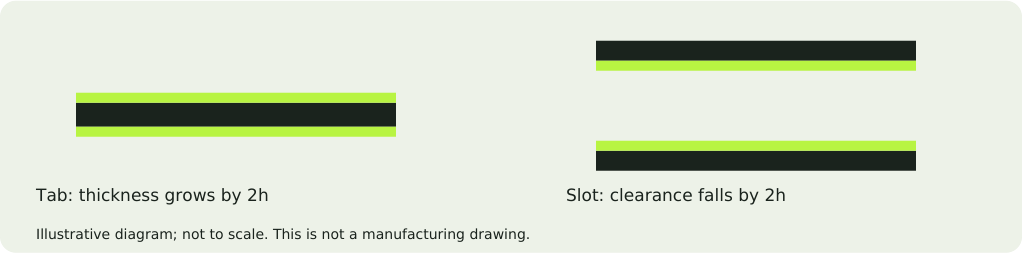
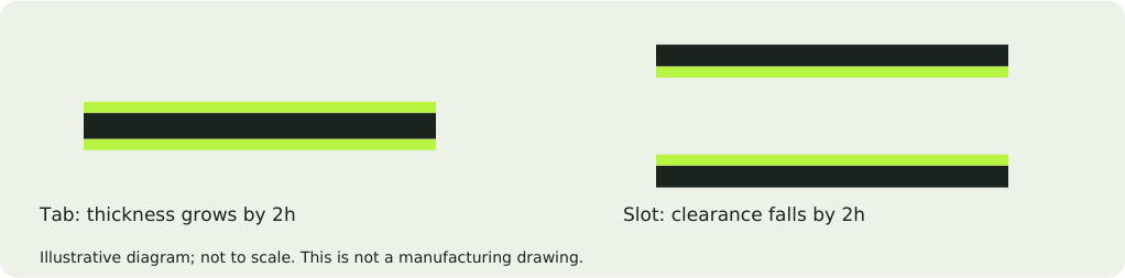
A slot coated on both opposing surfaces loses approximately twice the layer thickness from its clear width. A tab coated on both faces grows by the same effect. For a joint coated on both components, these effects accumulate.
Actual variation
The idealised calculation supports design but does not include all dimensional variation, burrs and local non-uniformity. Check part tolerances together with finishing-system tolerances. For a close fit, a finished sample is useful before production.
08 / Masking, threads and contacts+
Assembly areas
Identify threads, bores, recesses, sealing surfaces and contact faces that must remain uncoated. Supplement the 3D model with a PDF view or masking map. Colour alone does not define whether an area requires masking.
Electrical contact
For grounding or conductive contact, state area and function. Ordinary powder is not assumed conductive. Make and verify the contact according to design requirements; an unmasked screw hole alone does not guarantee electrical continuity.
Operation sequence
Establish whether threads and bores are made before finishing with masking, or afterwards with protection restored where needed. Cleaning a thread after coating can remove local protection. Include this in the manufacturing route rather than at receiving.
Masking, threads and contacts
Area
Instruction
Thread
Masking or agreed later operation
Fit bore
Final dimension and protected area
Sealing
Surface and coating criterion
Electrical contact
Position, function and verification
09 / Hanging and the curing cycle+
Hanging points
The part must be supported and positioned during processing. Identify areas where hanging marks are accepted and whether process holes are allowed. For a cosmetic face, discussing hanging points before cutting can avoid a visible defect.
Temperature and time
Curing follows the product technical datasheet; oven air temperature and actual part temperature are different. Mass and thickness affect heating. A generic time cannot be applied to every assembly without checking the system.
Assembly compatibility
Assess sensitive components, plastics, adhesives, fillers and enclosed volumes before processing. State whether the part can be disassembled. Repair of a finished coating is not automatically equivalent to a complete cycle on a prepared substrate.
10 / Appearance acceptance and measurement+
Sample and assessment conditions
For cosmetic products, agree a sample, viewing distance, lighting and orientation. Screens and photographs are not sufficiently stable colour and gloss references. For metallic effects or textures, orientation and process can influence perception.
Visible and hidden areas
Classify areas by appearance importance. A main visible face may have different requirements from an area hidden after assembly. Define whether hanging marks, local repairs or small imperfections are accepted and where; “perfect appearance” is not a measurable criterion.
Agreed inspection
If layer thickness, adhesion, colour or other tests are required, specify methods, areas and documents. A complete report is not assumed for every order. Results for a system or sample do not automatically replace verification of the requested batch.
Appearance acceptance and measurement
Check
To agree
Colour
Sample and comparison conditions
Appearance
Faces, distance and acceptable defects
Layer
Range and measurement points
Tests
Method, batch and requested report
11 / Packaging, repairs and maintenance+
Protect the final surface
Separators, edge protection and individual packaging reduce scratching risk. Avoid metal-to-metal contact and check whether film or packaging material can affect the finish. State whether products will be stored or installed immediately.
Installation
Screws, washers and tools can damage the layer. Plan contact faces and protective elements in the design. For outdoor coated parts, installation damage and water retention in joints can affect durability; assess installation details.
Repair and cleaning
If repair is needed, request a solution compatible with the applied system and required appearance level. Follow system cleaning instructions and avoid unvalidated aggressive agents. Local repair can differ in colour, texture or performance and must be accepted.
12 / Acceptance and packaging+
Checklist
Material; required system; service environment; RAL; texture; gloss; visible faces; masking; final dimensions; hanging points; acceptance criteria.
Production sample
For visible products, approve a representative sample and agree assessment conditions. Appearance requirements must be measurable and identical throughout the batch.
Protecting parts
State individual packaging, separators and sensitive areas. Avoid metal-to-metal contact in transport; include part-identification requirements.
English edition, 6 October 2026. Examples illustrate geometry and calculations. Materials, tooling, tolerances and finishes are confirmed for the specific project before production.